
Identify thermal barriers and thermal shortcuts in electronic designs: Mentor Graphics’ FloTHERM is the leading CFD thermal analysis solution for the electronics industry vertical.
FloTHERM V9 adds innovative post-processing techniques that open up a new dimension of thermal analysis, helping engineers understand why a design overheats. Two newly developed quantitative methods and display technologies assist FloTHERM V9 users in visualizing critical, historically abstract thermal features in their designs:
- *Barrier of Thermal Dissipation (Bn): Defines the flow path of high temperature airflow while showing the rejection of heat by airflow.
- *Cooling Shortcuts (Sc): Displays alternative, more efficient heat flow paths; in other words, shortcuts to the cooling area faster.
Finally, the Bn and Sc values help engineers understand what heat has dissipated out of the system, allowing them to redesign heat flux distribution plans to improve performance. So far, there is no way to identify a design’s thermal barriers and thermal shortcut opportunities. According to the design corrections made according to the Bn and Sc data, the new designs formed can not only clarify the heat dissipation obstacles, but also overcome these obstacles.
Explain The Mathematical Principles
The heat flow through the specified cross-sectional area is the heat flux (Heat Flux). The heat flux vector is always together with the temperature gradient vector. These two terms work in a CFD thermal analysis tool like FloTHERM like stocks on the stock market. Essentially, their interaction represents the thermal resistance index. At a given value of heat flux, the higher the gradient temperature, the greater the thermal resistance. At the same time, these two vector values are related to the FloTHERM analysis and are also parameters that support the heat dissipation distribution in the case of natural convection.
The length of the Heat Flux Vector arrow represents the heat flux, and similarly, the length of the Temperature Gradient Vector arrow represents the temperature gradient. The two vector relationships in this figure are far from reality and are just for the sake of explaining the mathematics behind the CFD analysis.
The thermal barrier value is the point where the two vectors intersect. As shown in Figure 1, at each point in space, when the heat flux vector and the temperature gradient vector arrive at the point at the same time, at that point, the Bn scalar value can be calculated. Assuming that the two vectors are in ideal positions (which is very unlikely in reality), Cos (θ) (angle cosine) = 1, and the Bn value is exactly the vector value. The units of Bn and Sc values are WdegC/m3 (Watts Celsius/m3)
Bn = Heat flux magnitude × Temperature gradient magnitude × sting bottlenecks.
A high Bn value indicates that a large amount of heat is trying to pass through a large thermal resistance. Needless to say, these are thermal “barriers”, and they often coexist with high temperature gradients.
The scalar for any point shortcut value is the quadrature of the heat flux and temperature gradient vectors. The large value of Sc indicates that the heat in the area does not move directly to the lower temperature area. These areas are where new heat transfer paths are created.
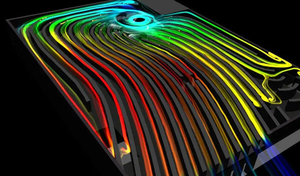
Looking at the board from a temperature distribution standpoint, hot areas of the BGA device may be marked with a color representing “overheating”, usually orange or red. But Figure 2 is not a heat distribution cloud map. It shows the Sc value, so the red area represents not the temperature, but an area that would benefit the most if better heat transfer paths were created. The Sc contour shows that local convective heat transfer is relatively efficient, so it presents a new opportunity for improvement: lowering the temperature can be achieved by adding a means of forced cooling – a common finned heat sink.
In a design project, Bn analysis pinpoints problem areas, while Sc analysis highlights solutions. The result is a greatly reduced junction temperature (Tj) within the BGA.
In another project, a similar component (heat sink) was soldered in the chassis as recommended by the original Sc analysis, reducing Tj by 74%; after the second Sc analysis, a more comprehensive The heat dissipation path, the junction temperature is further reduced by 58% based on the first improvement.
Engineers are confronted with increasingly complex wiring and thermal densities in all types of products, so thermal simulation is now a routine procedure in electronic design. FloTHERM version 9 easily detects thermal barriers and thermal shortcuts, an invaluable convenience for today’s time-constrained and budget-constrained design projects.