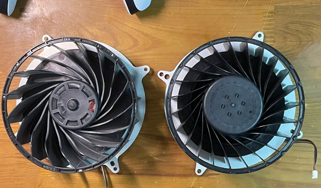
Combined with a practical example, this paper uses the FloTHERM electronic equipment thermal design simulation software of Mentor Graphics to study the effect of fan vortex on the heat dissipation of the power module, determine the relationship between the rotation direction of the fan and the flow field at the air outlet, and give the power module in the power module. Solutions to avoid this effect in thermal design.
Foreword
In the power electronics industry, due to the existence of a large number of power components, forced air cooling is widely used in this industry. Due to the characteristics of the products in this industry and their main application environment, when the power module or system chooses the cooling method of forced cooling, the axial flow fan is widely used. Because the working principle of the axial flow fan is to work through the motor, drive the blades connected to it to rotate at the speed given by the motor, thereby generating a certain pressure difference between the front and rear of the blades, driving the air around the blades along the motor shaft. movement in the direction. Therefore, the axial flow fan has the characteristics of low pressure head and large flow rate. Usually, when people choose an axial fan, they only consider the above-mentioned characteristics, and ignore a series of influences caused by the rotation of the axial fan blades on the air forced to flow. In fact, the fluid passing through the axial fan does not move in a single direction along the motor shaft, and also has a velocity motion component on the cross section of the fan blade perpendicular to the motor shaft. Therefore, the fluid driven by the axial flow fan is actually a flowing fluid that rotates forward with the motor shaft as the axis.
The fluid passing through the outlet of the axial fan is actually the fluid flowing forward along the axis, so what effect does the actual rotation direction of the fan have on the flow field behind it (the cooled area inside the power supply)? Combining an actual example of our products, this paper uses Mentor Graphics’ FloTHERM electronic equipment thermal design simulation software to study this problem, determine the relationship between the rotation direction of the fan and the flow field at the air outlet, and give the actual application process in the future. how to avoid or exploit this relationship.
Simulation Analysis Model
Under this model, we recalculate the two models by adjusting the rotational direction of the axial fan (swirl’s direction: clockwise or counter clockwise) without changing the meshing of the model. After the calculation is converged, by comparing the change of the flow field inside the module and the cross-sectional distribution of the temperature field in the two cases, the effect of different rotation directions of the fan on the heat dissipation of the entire module is explained.
Simulation Results Analysis And Conclusions
Comparing the above two analysis results, we can find that: in the analysis process of this model, the rotation direction of the fan has a great influence on the distribution of the flow field and temperature field inside the module. From the perspective of the flow field, because the size of the rectifier bridge part of this model is relatively low, and the PFC radiator part is relatively high, in this case, the rotation direction of the fan has a very significant impact on the flow field. Comparing Figure 5 and Figure 8, it can be clearly found that when the fan rotates clockwise, the vortex around the rectifier bridge radiator is very small, and the flow field is relatively smooth, which is beneficial to the heat dissipation of the rectifier bridge radiator, as shown in Figure 5; However, when the fan rotates counterclockwise, there are many vortices around the rectifier bridge radiator, which is not conducive to the heat dissipation of the rectifier bridge radiator, as shown in Figure 8. Of course, these differences can also be further confirmed by the distribution of the temperature field of the module cross-section, as shown in Figure 6 and Figure 9.
By carefully observing the flow field animation of the fan in different rotation directions, we can see that the reason why the fan rotation direction affects the subsequent flow field distribution is that the rotation direction of the fan determines the spiral direction of the fluid flowing in a spiral at the fan outlet. . Therefore, we should make full use of this phenomenon in the actual application process, try to avoid the layout that is not conducive to the heat dissipation of key power components or large-loss power components inside the module, and ensure the rationality and reliability of thermal design.
Summarizing the relevant data provided by the fan supplier, we can obtain the following simple method to determine the influence of the fan rotation direction on the flow field: according to the principle of left-hand rotation, the direction of the thumb is the macro flow direction of the fluid, and the bending direction of the other four fingers is the fan The direction of rotation of the flow field at the outlet. In the layout of power components, according to the left-handed spiral principle, as long as we arrange the key components in the direction of the four curved thumbs, we can completely avoid the adverse effects of component heat dissipation caused by the rotation direction of the fan.
Of course, the above analysis is only applicable to the occasions where the axial fan is used for forced air cooling. In the case of exhaust cooling, since the change of the flow field of the fan outlet has no effect on the air inlet, the rotation direction of the fan has no effect on the heat dissipation inside the module.


