
Aluminum profiles have the advantages of high specific strength, beautiful appearance, corrosion resistance, and easy recycling. They are widely used in construction, railway transportation, aerospace and communications. Aluminum radiator is extruded, welded or assembled from 6063 aluminum alloy, and has become the first choice to gradually replace other radiator products in modern life. HyperXtrude from Altair is a professional software for simulating extrusion processes and guiding extrusion die design. HyperXtrude can simulate complex plastic deformation, material flow and heat transfer process [1]. This paper takes a set of molds in actual production as an example, uses the HyperXtrude software based on the ALE algorithm to simulate the flow of metal in the mold, and analyzes the problems that the mold may encounter in the extrusion process.
The Description Of The Problem
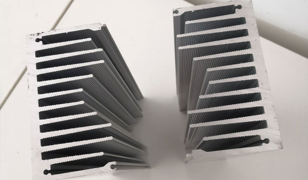
The radiator profiles studied in this paper have large external dimensions, large wall thickness differences, flat and wide shapes, and asymmetrical left and right. The heat sinks are assembled by tooth-shaped occlusion, which requires high forming precision and is difficult to produce. This product is mainly used in the heat dissipation of air conditioners. It has the characteristics of large heat dissipation area, excellent air-cooled heat dissipation performance, and its shape conforms to the size of its heat dissipation space. As shown in Figure 1a, the material head of the initial trial mold. Preliminary judgment shows that the flow velocity on both sides of the profile is fast, the flow velocity in the place with screw holes is also faster, and the two ribs in the middle are slightly slower, resulting in the profile cannot be formed well. Figure 1b shows the middle section extruded from the trial die. After stretching and straightening, the profile does not meet the assembly requirements. Figure 1c shows the assembly requirements for the profile, which requires a levelness of 180. It can be seen that the main problem of profiles is the problem of shape and size tolerance.
The traditional profile extrusion die design mainly relies on engineering analogy and design experience, resulting in a lot of waste of manpower and material resources, and seriously affecting production efficiency and product quality. The numerical simulation technology is introduced into the extrusion die design. By simulating the mold tryout on the computer, the numerical simulation method can simulate the actual extrusion process, and obtain physical quantities such as speed, temperature, stress and strain that are difficult to measure on the spot. Whether the profile products have defects such as twisting, bending, and waves, so as to evaluate whether the process and mold structure design is reasonable, modify the process and design parameters in time, and replace the time-consuming and laborious process of mold trial and repair [2-4].
The Establishment Of Finite Element Model
2.1 Meshing
Numerical simulation of the extrusion process [5-6]. HyperMesh software is used to pre-process the model. Triangular prism meshes are used at the outlet of the working belt and profiles, tetrahedral meshes are used for the mold, and tetrahedral meshes are used for the blanks, distribution holes and welding chamber areas. The degree of deformation is determined, because the deformation of the material near the working belt is relatively severe, and the unit division is relatively fine, while the material in the bar part only has pier rough deformation, and the unit division is relatively coarse, and the mesh of the shunt hole and the welding room should be properly transitioned. This not only ensures the analysis accuracy, but also effectively controls the number of elements and saves the calculation time. The finite element mesh model is shown in Figure 2, and the mesh parameters are shown in Table 1.
2.2 Parameter setting
The constraints of the extrusion die are set by boundary conditions [7~8]. The extruded metal is AA6063, the die material is H13; the temperature of the extrusion cylinder is set to 430°C, the die is preheated to 450°C, the preheating temperature of the metal blank is set to 480°C, and the extrusion speed is set to 5mm/s; Friction condition: Coulomb friction model is used in the working belt area, the friction coefficient is taken as 0.3, and the stick friction model is used on the surface of the extrusion cylinder and die.
The Analysis Of Simulation Results
3.1 Displacement Distribution
Figure 3 shows the displacement cloud map in the X direction of the profile outlet. The blue part of the profile swings in the negative direction of X, and the maximum displacement reaches -2.5mm, and the red part swings in the positive direction of X, and the maximum displacement reaches 3.028mm. The yaw is an important reason that the subsequently extruded profiles cannot be assembled, which may be due to the unreasonable design of the upper and lower die working belts here, so that the inner and outer walls of the profiles cannot flow out of the die holes at the same time. The displacement deviation of other parts of the profile is relatively uniform and will not affect the assembly.
3.2 Flow Velocity Distribution
Figure 4 shows the velocity vector distribution diagram of the metal flowing through the shunt hole and the welding chamber area. The die hole is designed to have a certain wide angle, and the metal is equivalent to flowing forward in the form of a ramp in the die hole. Due to the effect of friction, the metal close to the die wall is almost adhered to the surface of the die, and the metal flow is more aluminum. The friction with aluminum reduces the resistance relatively much. Since the area of the middle shunt hole is smaller than the area of the surrounding shunt holes, when the metal bypasses the shunt bridge and flows into the shunt hole, the flow rate is correspondingly lower; The metal of each shunt hole gathers here, and the metal continues the flow trend at the shunt hole, showing that the flow velocity at the periphery is relatively slow, while that in the middle is relatively fast, and the metal flows uniformly to the exit of the die hole. The accumulation of a large amount of metal, the flow speed is also large, the friction between the flowing metal and the surface of the mold is severe, and the damage to the working belt of the die hole is also large.
Regions with slower flow velocity create compressive stress and faster regions create tensile stress. The flow speed of the two ribs in the middle is very slow, the metal flow rate at the two screw holes is relatively large, and the middle part forms an inward pulling force when forming; , resulting in a certain distortion of the deformation of the profile outlet. The deformation of the outlet is in good agreement with the material head of the trial mold.
3.3 Temperature Distribution
Figure 6 shows the temperature distribution at the shunt hole, welding chamber and working belt. The metal on both sides of the profile flows faster, the heat of the metal gathers more, and the temperature on both sides is higher; the metal in the middle, blocked by the mold core, can dissipate heat in time, and the metal flow rate is slow, so the temperature is relatively low; work at the outlet At the belt, the high-temperature metal is formed through the die hole, and the severe friction will generate a lot of heat, most of which is retained in the metal, and a small part is dissipated through the die, and the temperature is the highest. The change of temperature gradient has a great influence on the quality of the profile. At the temperature boundary, it is easy to produce the color temperature during the subsequent cooling of the profile extrusion, or the uneven structure, which directly affects the quality of the profile.
3.4 Mold Analysis
Figure 7 shows the stress distribution of the mold. The overall stress distribution of the mold is small and uniform, the stress of the upper mold is smaller than that of the lower mold, and the stress is concentrated at the working belt. In the positive direction of extrusion, the die is subjected to the pressure of the extruder, and the tensile force of the profile flowing out of the die hole is effected. The upper die is squeezed by the extrusion pad, the shunt bridge is sheared by the flowing metal, and the die core is subjected to unequal pressure at both ends, which may cause deflection. The working belt is a weak area and is severely rubbed by the flowing metal. more vulnerable to damage. The working belt of the lower die is subjected to the tensile stress of the profile during the extrusion process, which has a great influence on the working belt at the cantilever, and the maximum stress appears at the small cantilever.
Modify
4.1 Modifications
Through the analysis of the numerical simulation, it can be concluded initially that the lack of material supply at the middle two ribs leads to the slow flow rate. Combined with the discharge of the material head and the simulation situation, the mold has been slightly modified. Through the stress analysis of the mold, we can see that , there is a local stress concentration phenomenon at the working belt. For the upper mold, there are several modifications. First, the area of the two middle shunt holes can be appropriately increased; second, the inclination under the mold core can be increased to make it easier for the metal to flow forward; finally, the working belt can be adjusted. For the lower die, a choke table can be set at the corresponding four sides of the die hole to appropriately slow down the metal flow rate and appropriately modify the size of the working belt.
Enlarging the area of the shunt hole is easy to cause large fluctuations in the flow rate, and considering the processing factors, it is not recommended to use it; it is more convenient to increase the drainage of the lower mold core with an electric spark, and appropriately reduce the working belt of the two middle ribs. Height, the working belt of the middle two ribs is reduced from 2.8mm to 2.4mm; a choke table is added to the four sides of the lower die, and the working belt on both sides of the profile is increased by 0.4mm. Figure 8 shows the modified lower die.
4.2. Modified Results
Steady-state simulations were carried out on the modified mold using the same process parameters. It can be found that the velocity gradient distribution of the profile outlet velocity at the outlet section is uniform, and an extrusion part with a flush end face can be obtained. Figure 9 shows the distribution of flow velocity at the outlet of the profile after modification of the mould. After the actual trial of the revised mould, the flow velocity gradient has been improved. Although the two sides are slightly faster, the middle is still a little slow, but it meets the requirements of profile forming and can be produced smoothly. After the profiles are sprayed, the two profiles can be assembled well, as shown in Figure 10 for the final qualified profile product.
Conclusion
- Through numerical simulation, the profile displacement, metal flow velocity, temperature and die force in the extrusion process are analyzed, and it is found that the working belt is an important factor affecting the profile forming.
- Using the method of promoting flow on the upper die, adding a choke table on the lower die and adjusting the length of the working belt, the flow of the metal in the die can be effectively adjusted, so that the velocity distribution of the exit section of the profile is more uniform, and the dimensional accuracy of the profile is also obtained. improve.
- Through the HyperXtrude extrusion simulation software of Altair, the flow of metal in the mold can be simulated, and the possible problems in the extrusion process of aluminum profiles can be predicted, and the parts that may fail during the operation of the mold can effectively guide the extrusion mold. design.